2. Tutorial on creation of geometric content
2.1. First step
To make these exercises, you must launch ipython with the following option
terminal_linux:~$ ipython --gui=qt
Warning
If you do not use this option, you will certainly have problems if you want to display your results with the viewer.
Now you must import all modules from plantgl
from openalea.plantgl import *
If you have any remark, question, suggestion, critics about this tutorial, send me an email at: chloe.xavier@gmail.com
Now, as the best way to learn is to practice, we will do some exercises. We indicate what is useful in the documentation.
2.2. Exercises
2.2.1. Hello World
- Invoke help on the
Boxprimitive, what are the possible constructor arguments ? - Look at the plantgl doc on the web.
- Create a
Sphereof radius 5. - Display it on the
Viewer.
Your result should be :

Note
In the viewer, you can change the camera angle by drag and drop, change the light direction by pressing ctrl and drag and drop, and get closer or further by scrolling.
2.2.2. Material
Create a shape with the previous sphere to associate a red material.
Your result should be :

Hint : Use Shape and Material.
2.2.3. Transformation
Create a Sphere centered at point (-2,0,0).
Your result should be :
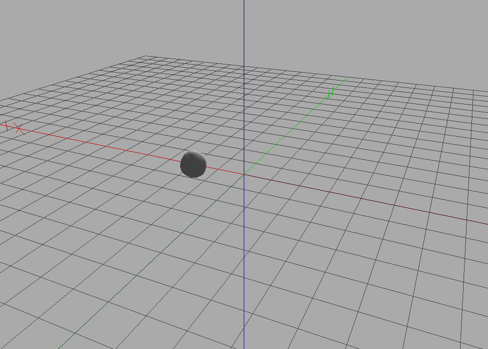
Hint : Invoke help on Translated.
2.2.4. Scene
Display a scene with two spheres, one red, one yellow, respectively positioned at (-5,0,0) and (-2,0,1).
Your result should be :
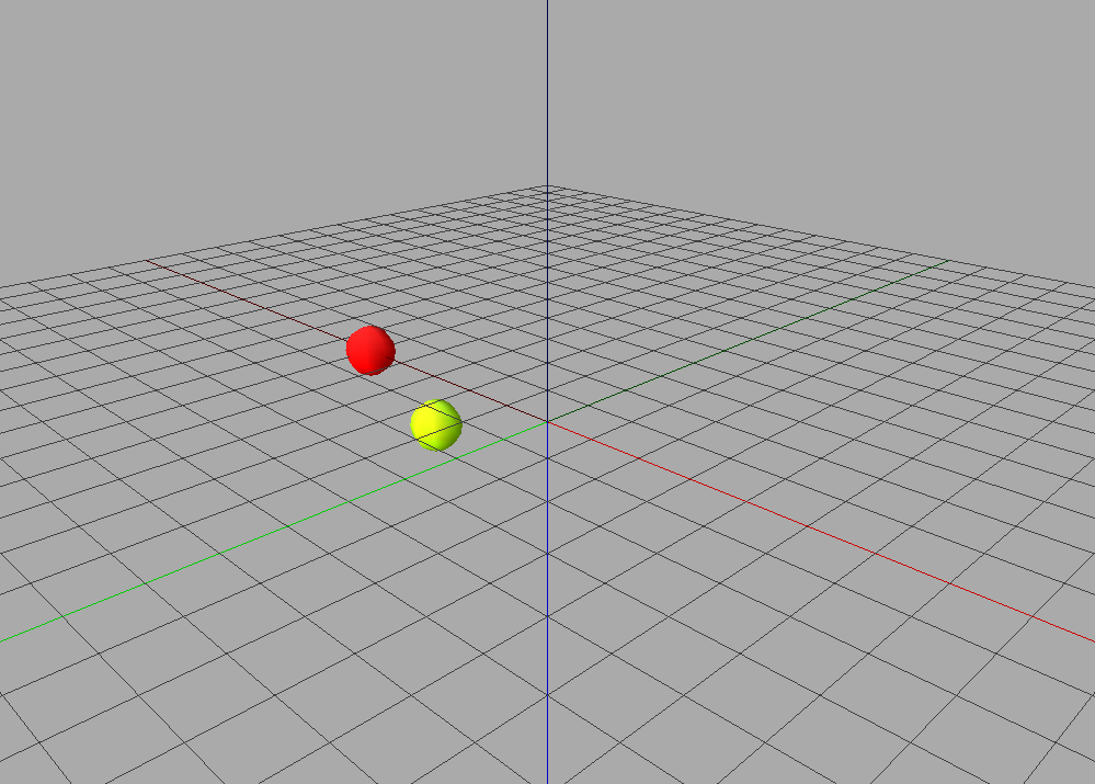
Hint : Invoke help on Scene.
2.2.5. Instantiation
In the previous scene, use the same sphere primitive for the translations. Change the radius of the sphere and observe the effect on the scene.

2.2.6. Mesh
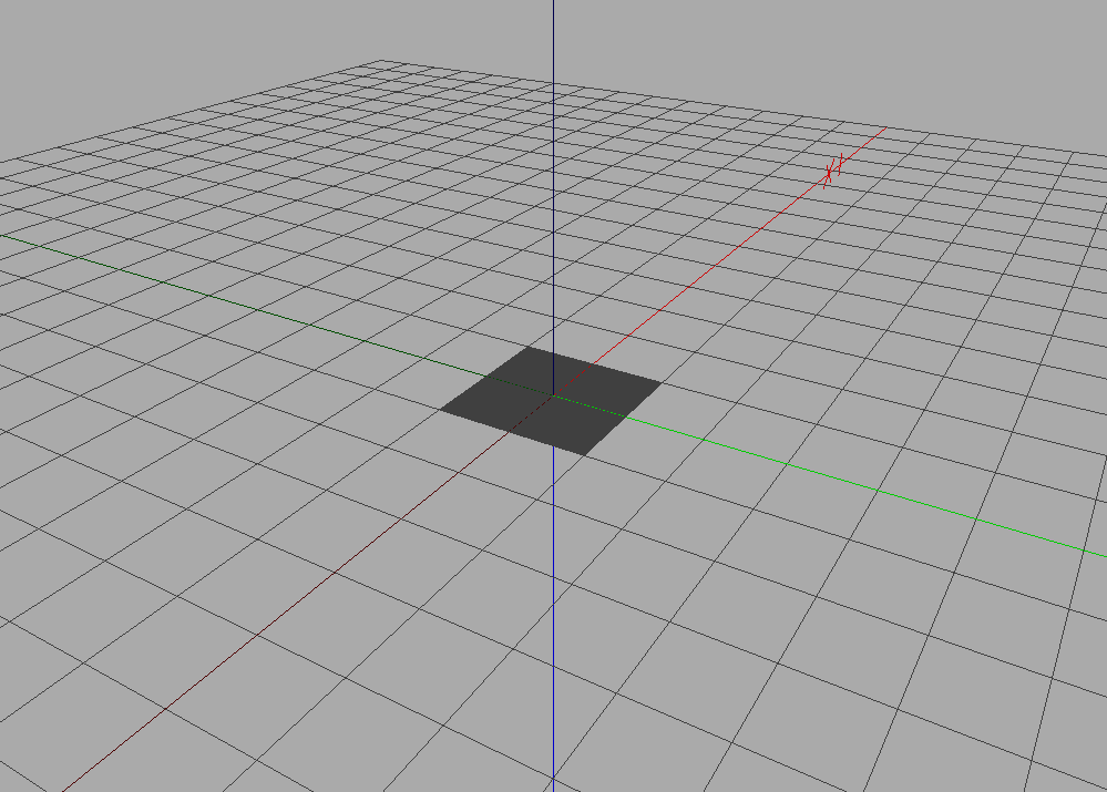
- Create a square with
QuadSet - Add different colors to the vertices of the square in the quadset
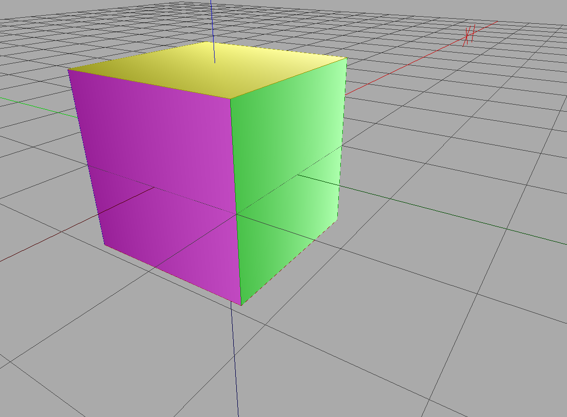
- Create a box with
QuadSetwith different colors for each face - Create a box with
QuadSetwith a different color associated to each point in each face

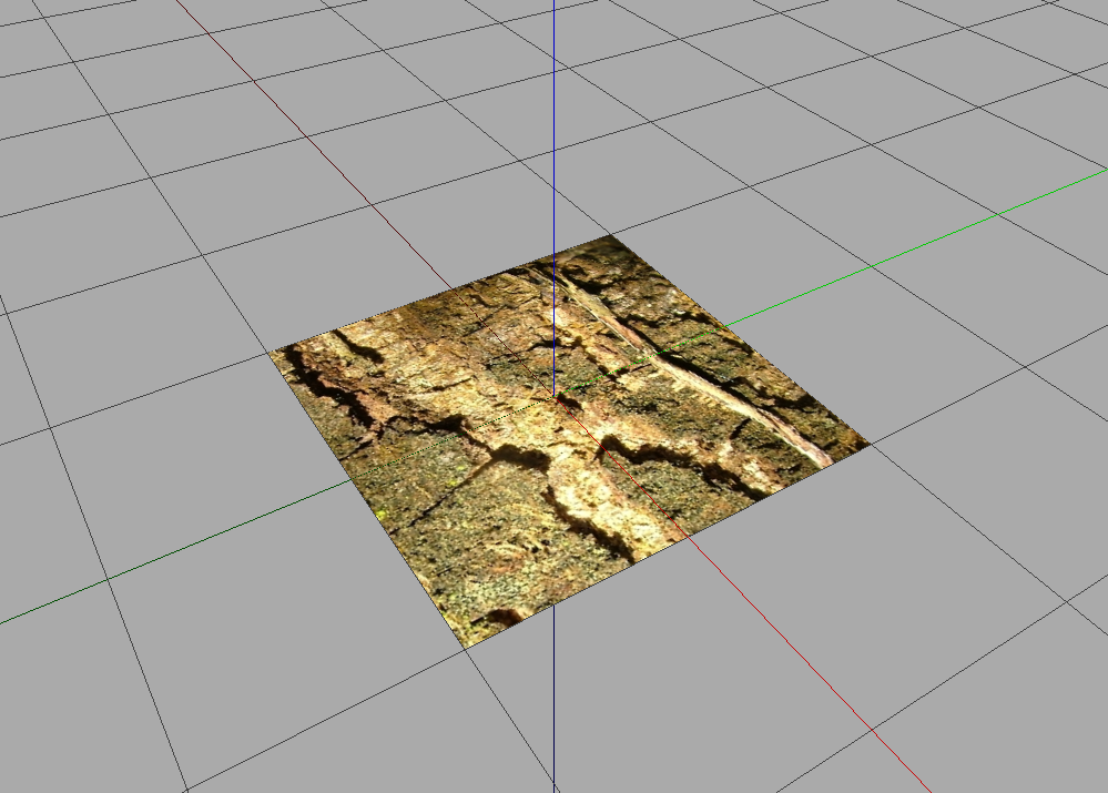
2.2.7. Texture and Billboard
Add texture coordinates to the vertices of the square in the
QuadSetto display an image. You can use this image :
Hint : Create a
Shapewith your square as a geometry andImageTextureas a material.Use transparency to display a leaf onto a square . You can use for instance this image :

Display the wood texture on the square but only a part of the picture (half of its width and height starting from 1/4,1/4).
Display always the same image (with same orientation!) on the 6 faces of a cube.
Create a cross like shape with 5 squares using
QuadSetand display part of the texture on each square.
You should have as results :


2.2.8. Discretisation
- Create a
QuadSetcorresponding to a cylinder - Create a
TriangleSetcorresponding to a cylinder - (Difficult) Create a
Sphereas a truncated icosahedron
Your results should be alike this :
2.2.9. Hulls
Create python function to display a growing
AsymmetricHull


Create profiles with positive x coordinates with
Polyline2D,BezierCurve2D,NurbsCurve2D


Create a
Swunghull with previous profiles positioned at different angles between [0;2*pi] to get something like
Create a circle with Polyline2D.Circle and a closed profile representing silhouette of a tree.

With these 2 profiles, create an
ExtrudedHullto get something looking like :
2.2.10. Generalized Cylinder
With a circle and 3D line create a branch with an Extrusion. Your result should be something like :

2.2.11. Positioning objects
- Create a trunk of 2 meter with a cylinder and regular lateral pair of leaves at every 50 cm.
Hints : Use
Translated,AxisRotated,EulerRotated, etc. - Same with size of leaves diminishing.
Hints : Use
Scaled. - Same with a trunk with an elbow of 30 degree in the middle.


Hints : Take care of the order in which the transformations are performed !
2.3. Solutions
2.3.1. Solution for Hello World
The python script to get help on Box is
from openalea.plantgl.all import *

help(Box)
b = Box(1,2,4)
Viewer.display(b)
Thanks to the help, we see that args for initializing a Box are the scaling in all 3 directions x, y and z. We call it and display it to obtain as a result :

And then to create the sphere of radius 5, we call
from openalea.plantgl.all import *

s = Sphere(5)
Viewer.display(s)
To obtain
2.3.2. Solution for Material
To associate a red material to a sphere, the python script is :
from openalea.plantgl.all import *

s1 = Sphere(3)
m = Material("red", Color3(150,0,0))
Shape1 = Shape(s1,m)
Viewer.display(Shape1)
and the resulting image is :
2.3.3. Solution for Transformation
To translate a sphere, the python script is :
from openalea.plantgl.all import *

s1 = Sphere()
s2 = Translated(2,0,0,s1)
Viewer.display(s2)
and the resulting image is :
2.3.4. Solution for Scene
To make a scene with two different spheres, the python script is :
from openalea.plantgl.all import *

s = [Sphere() for i in range(2)]
m = [Material(Color3(150,0,0)), Material(Color3(100,150,0))]
s = [Translated(-5,0,0,s[0]),Translated(-3,0,1,s[1])]
shapes = [Shape(sp,m[i]) for i,sp in enumerate(s)]
scene = Scene(shapes)
Viewer.display(scene)
and the resulting image is :
2.3.5. Solution for Instantiation
To make a scene with two different spheres from the same sphere primitive, the python script is :
from openalea.plantgl.all import *

s = Sphere(2)
m = [Material(Color3(150,0,0)), Material(Color3(100,150,0))]
s = [Translated(-5,0,0,s),Translated(-3,0,1,s)]
shapes = [Shape(sp,m[i]) for i,sp in enumerate(s)]
scene = Scene(shapes)
Viewer.display(scene)
and the resulting image is :
2.3.6. Solution for Mesh
To get the square with colors to each vertex, the python script is:
from openalea.plantgl.all import *

# A list of the coordinates of the square
points = [(-1,-1,0),(1,-1,0),(1,1,0),(-1,1,0)]
# A list of colors
colors = [Color4(150,0,0,155),
          Color4(150,150,0,155),
          Color4(0,150,0,155),
          Color4(0,150,150,155)]
# A list of directions for the normals
normals = [(0,0,1) for i in range(4)]
# A list of indices that set the indices for the quads
indices = [(0, 1, 2, 3)]
# Creation of the quadset
carre = QuadSet(points,indices,normals,indices,colors)
Viewer.display(carre)
and the resulting image is:

The list of points indicates the coordinates of the vertices, each tuple of indices indicates which point are used for a specific quad, linked in the given order. We set the normals, indicate colors and associate with indices each color to a different vertex.
Now we compute a cube with a color for each face. The python script is:
from openalea.plantgl.all import *

# list of points
points = [(-1,-1,-1), # coordinates of bottom right corner
          (1,-1,-1),
          (1,1,-1),
          (-1,1,-1),
          (-1,-1,1),
          (1,-1,1),
          (1,1,1),    # coordinates of top left corner
          (-1,1,1)]

# list of indices to make the quads from the points
indices = [(0, 1, 2, 3), # indices for bottom face
           (4, 5, 6, 7), # indices for top face
           (0, 1, 5, 4), #
           (1, 2, 6, 5), # indices for
           (2, 3, 7, 6), # side faces
           (3, 0, 4, 7)] #

# list of colors
colors = [Color4(150,0,0,155),
          Color4(150,150,0,155),
          Color4(0,150,0,155),
          Color4(0,150,150,155),
          Color4(0,0,150,155),
          Color4(150,0,150,155)]

# construction of the geometry
cube = QuadSet(points,indices)
# adding information to the geometry
cube.colorList = colors

# list of indices to associate a vertex in a face to a color
# here each face will be associated to only one color of the list
cube.colorIndexList = [(0,0,0,0),
                       (1,1,1,1),
                       (2,2,2,2),
                       (3,3,3,3),
                       (4,4,4,4),
                       (5,5,5,5)]
Viewer.display(cube)
for the result :
We define a list of 8 vertices, then a list of squares using those vertices. Then we define a list of 6 colors, and the color indices allow to associate a color for a vertex in a given square. For the first square, vertex v1 is associated with color 0, for the second square it is associated to color 1, for the third adjacent square it is associated with color 4. If you let colorIndexList to default (to none), a color must be associated to each vertex.
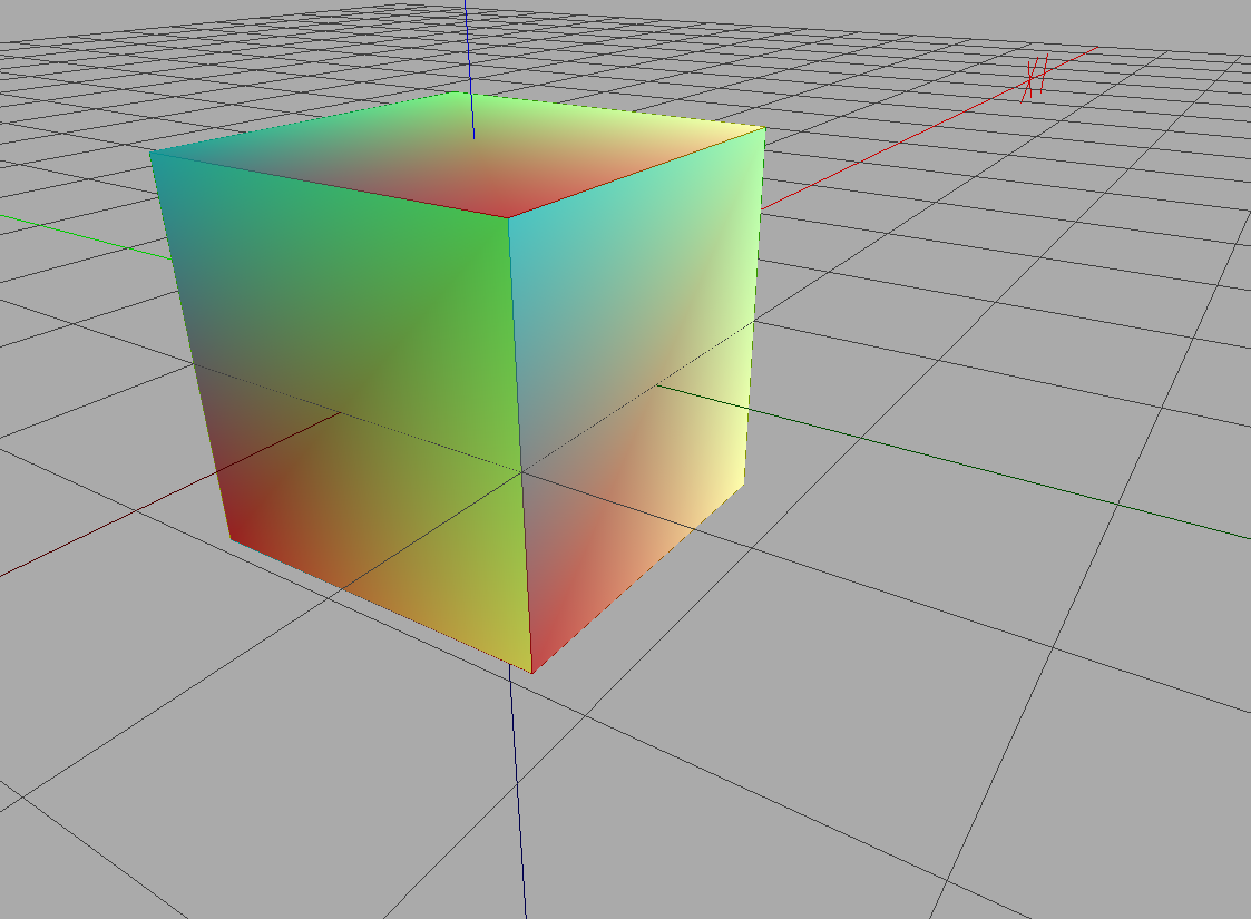
If we want to compute now a cube with, for each face, a color per vertex, we will use the python script :
from openalea.plantgl.all import *

# list of points
points = [(-1,-1,-1),  # coordinates of bottom right corner
          (1,-1,-1),
          (1,1,-1),
          (-1,1,-1),
          (-1,-1,1),
          (1,-1,1),
          (1,1,1),    # coordinates of top left corner
          (-1,1,1)]

# list of indices to make the quads from the points
indices = [(0, 1, 2, 3), # indices for bottom face
           (4, 5, 6, 7), # indices for top face
           (0, 1, 5, 4), #
           (1, 2, 6, 5), # indices for
           (2, 3, 7, 6), # side faces
           (3, 0, 4, 7)] #

# list of colors
colors = [Color4(150,0,0,155),Color4(150,150,0,155),
          Color4(0,150,0,155),Color4(0,150,150,155)]

# construction of the geometry
cube = QuadSet(points,indices)
# adding information to the geometry
cube.colorList = colors

# list of indices to associate a vertex in a face to a color
# here each face will be alike, with top left corner in color 0,
# top right corner in color 1, bottom right corner in color 2
# and bottom left corner in color 3
cube.colorIndexList = [(0,1,2,3) for i in range(len(indices))]
Viewer.display(cube)
for the result :
2.3.7. Solution for Texture and Billboard
Here is the python script to get a textured squared :
from openalea.plantgl.all import *

# list of points
points =  [(-1,-1,0),
           (1,-1,0),
           (1,1,0),
           (-1,1,0)]
# list of indices
indices = [(0, 1, 2, 3)]
# creating the geometry
carre = QuadSet(points,indices)
# creating the texture in a material
tex = ImageTexture("./textures/wood_texture.png")
# the texture coordinates that we will use
texCoord = [(0,0),(0,1),(1,1),(1,0)]
# how texture coordinates are associated to vertices
texCoordIndices = [(0,1,2,3)]
# adding information to the geometry
carre.texCoordList = texCoord
carre.texCoordIndexList = texCoordIndices
# associating the geometry and the material in a shape
sh = Shape(carre,tex)
Viewer.display(sh)
for the result :
It is the same python script to get a textured squared, with a texture which as an alpha channel :
from openalea.plantgl.all import *

# list of points
points = [(-1,-1,0),
          (1,-1,0),
          (1,1,0),
          (-1,1,0)]
# list of indices
indices = [(0, 1, 2, 3)]
# creating the geometry
carre = QuadSet(points,indices)
# creating a texture from a file
tex = ImageTexture("./textures/leaf_tex.png")
# the coordinates of the texture that we may use
texCoord = [(0,0),(0,1),(1,1),(1,0)]
# how we associate the coordinates of the texture to
# the vertices of the quad
texCoordIndices = [(0,1,2,3)]
# adding those informations to the geometry
carre.texCoordList = texCoord
carre.texCoordIndexList = texCoordIndices
# associating the texture and the geometry in a shape
sh = Shape(carre,tex)
Viewer.display(sh)
for the result :
It is nearly the same python script to have only part of the texture on the square. All you need to do is change the texture coordinates :
from openalea.plantgl.all import *

# list of points
points =  [(-1,-1,0),
           (1,-1,0),
           (1,1,0),
           (-1,1,0)]
# list of indices
indices = [(0, 1, 2, 3)]
# creating the geometry
carre = QuadSet(points,indices)
# creating the texture
tex = ImageTexture("./textures/wood_texture.png")
# the texture coordinates that we will use
texCoord = [(0.25,0.25),(0.25,0.75),(0.75,0.75),(0.75,0.25)]
# associating the coordinates and the vertices
texCoordIndices = [(0,1,2,3)]
# adding the information to the geometry
carre.texCoordList = texCoord
carre.texCoordIndexList = texCoordIndices
# associating the material and the geometry
sh = Shape(carre,tex)
Viewer.display(sh)
for the result :
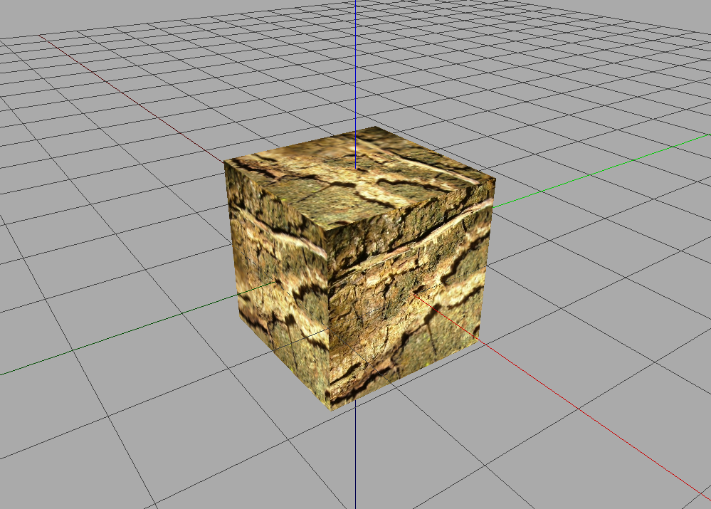
To get a textured cube, here is the python script :
from openalea.plantgl.all import *

# list of points
points = [(-1,-1,-1),
          (1,-1,-1),
          (1,1,-1),
          (-1,1,-1),
          (-1,-1,1),
          (1,-1,1),
          (1,1,1),
          (-1,1,1)]
# list of indices
indices = [(0, 1, 2, 3),
           (4, 5, 6, 7),
           (0, 1, 5, 4),
           (1, 2, 6, 5),
           (2, 3, 7, 6),
           (3, 0, 4, 7)]
# creation of the geometry
cube = QuadSet(points,indices)
# creation of a texture from a file
tex = ImageTexture("./textures/wood_texture.png")
# the texture coordinates that we will use
texCoord = [(0,0),(0,1),(1,1),(1,0)]
# how we associate texture coordinates to vertices in a quad
texCoordIndices = [(0,1,2,3) for i in range(len(indices))]
# adding those informations to the geometry
cube.texCoordList = texCoord
cube.texCoordIndexList = texCoordIndices
# associating the geometry and the material in a Shape
sh = Shape(cube,tex)
Viewer.display(sh)
for the result :
And to have a textured cross, with only part of the texture here is the script :
from openalea.plantgl.all import *

# list of vertices
points = [(-1,1,0),(-1,3,0),
          (1,3,0),(1,1,0),
          (3,1,0),(3,-1,0),
          (1,-1,0),(1,-3,0),
          (-1,-3,0),(-1,-1,0),
          (-3,-1,0),(-3,1,0)]
# list of indices to make the quads
indices = [(0, 1, 2, 3),
           (3, 4, 5, 6),
           (6, 7, 8, 9),
           (9, 10, 11, 0),
           (0, 3, 6, 9)]
# creating the geometry
cross = QuadSet(points,indices)
# creating the textures from files in materials
tex = ImageTexture("./textures/wood_texture.png")
tex2 = ImageTexture("./textures/leaf_tex.png")

# the coordinates of the texture to use
texCoord = [(0.33,0.66),(0.33,0.99),
            (0.66,0.99),(0.66,0.66),
            (0.99,0.66),(0.99,0.33),
            (0.66,0.33),(0.66,0),
            (0.33,0),(0.33,0.33),
            (0,0.33),(0,0.66)]
# how the coordinates are associated with the vertices
texCoordIndices = [(0, 1, 2, 3),
                   (3, 4, 5, 6),
                   (6, 7, 8, 9),
                   (9, 10, 11, 0),
                   (0, 3, 6, 9)]

# adding the information to the geometry
cross.texCoordList = texCoord
cross.texCoordIndexList = texCoordIndices
cross2 = Translated(-7,0,0,cross)
# associating the different textures to the same geometry
sh = [Shape(cross,tex), Shape(cross2,tex2)]
Viewer.display(Scene(sh))
for the result :
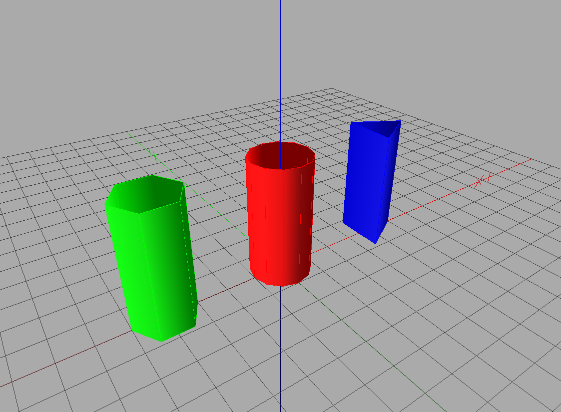
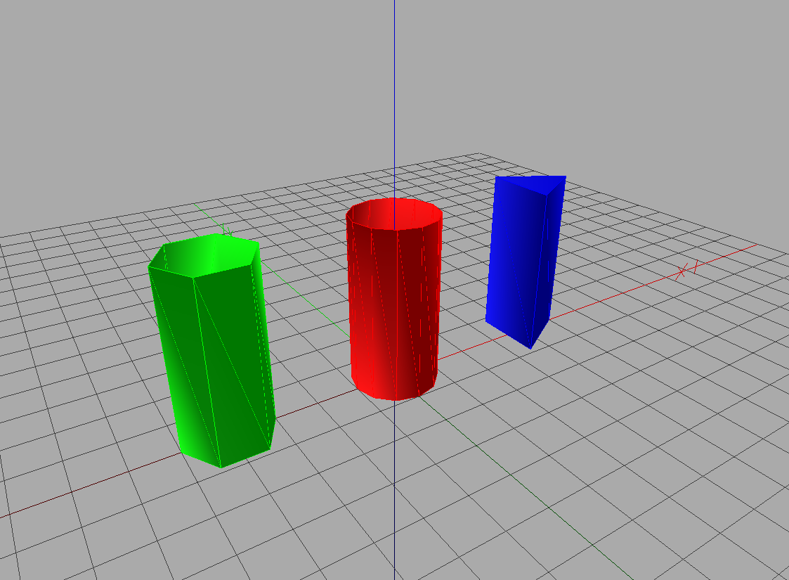
2.3.8. Solution for Discretisation
Here is the python script to get a cylinder with QuadSet :
from math import cos
from math import sin
from math import pi
from openalea.plantgl.all import *

def quad_cyl(radius, height, slices = 12):
    """ quad_cyl(radius, height) makes a cylinder with quads as primitives
                             with height height and radius radius """
    # we create the empty lists of points and indices
    points = []
    indices = []
    for i in range(slices):
        # we had 2 points at each iteration, the top and bottom
        # of a slice inn the cylinder, after a rotation of 2*pi
        # over the number of slices
        points += [(radius*cos(2*i*pi/slices),radius*sin(2*i*pi/slices), 0),
                   (radius*cos(2*i*pi/slices),radius*sin(2*i*pi/slices), height)]
        # we set the indices, each quad joining two slices
        if i is not (slices -1):
           indices += [(2*i,2*i+1,2*i+3,2*i+2)]
        else:
           indices += [(2*i,2*i+1,1,0)]
    # we create the geometry
    cyl = QuadSet(points,indices)
    return cyl

# The same cylinder with 3 different discretizations
cyl1 = quad_cyl(1,4)
cyl2 = Translated(-4,0,0,quad_cyl(1,4,6))
cyl3 = Translated(4,0,0,quad_cyl(1,4,3))

m1 = Material(Color3(150,0,0))
m2 = Material(Color3(0,150,0))
m3 = Material(Color3(0,0,150))

shapes = [Shape(cyl1,m1), Shape(cyl2,m2), Shape(cyl3,m3)]
Viewer.display(Scene(shapes))
for the result :
Here is the python script to get a cylinder with TriangleSet :
from math import cos
from math import sin
from math import pi
from openalea.plantgl.all import *

def tri_cyl(radius, height, slices = 12):
    """ tri_cyl(radius, height) makes a cylinder with triangles
                as primitives with height height and radius radius """
    points = []
    indices = []
    for i in range(slices):
        points += [(radius*cos(2*i*pi/slices),radius*sin(2*i*pi/slices), 0),
                   (radius*cos(2*i*pi/slices),radius*sin(2*i*pi/slices), height)]
        if i is not (slices -1):
           indices += [(2*i,2*i+1,2*i+2),(2*i+1,2*i+2,2*i+3)]
        else:
           indices += [(2*i,2*i+1,0),(2*i+1,0,1)]
    cyl = TriangleSet(points,indices)
    return cyl

cyl1 = tri_cyl(1,4)
cyl2 = Translated(-4,0,0,tri_cyl(1,4,6))
cyl3 = Translated(4,0,0,tri_cyl(1,4,3))

m1 = Material(Color3(150,0,0))
m2 = Material(Color3(0,150,0))
m3 = Material(Color3(0,0,150))

shapes = [Shape(cyl1,m1), Shape(cyl2,m2), Shape(cyl3,m3)]
Viewer.display(Scene(shapes))
for the result :
As you can see, there is already a class to create a cylinder. Why should that be interesting to do a cylinder with QuadSet or TriangleSet ? Well, doing it with QuadSet and TriangleSet will give you more freedom to apply a material (texture or colors) on the geometry.
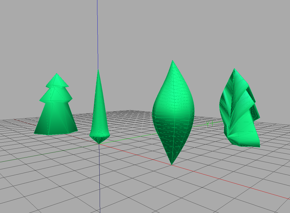
2.3.9. Solution for Hulls
A little python script to display 3 hulls with growing volume :
from openalea.plantgl.all import *

# First hull with bottom point (0,0,-1), top point (0,0.3,3.8)
# With side points (0.5,0,0.3), (0,0.9,0), (0.6,0,0.1), (0,0.8,-0.3)
# With tangent at bottom 0.9, at top 0.8
hull = AsymmetricHull(0.5,0.9,0.6,0.8,0.3,0.,0.1,-0.3,(0,0,-1),(0,0.3,3.8),0.9,0.8)
green = Material(Color3(0,150,0))

scene = Scene()
scene += Shape(Translated(-8,0,0,hull),green)

# We do the same with a bigger tangent for top
hull = AsymmetricHull(0.5,0.9,0.6,0.8,0.3,0.,0.1,-0.3,(0,0,-1),(0,0.3,3.8),0.9,1.2)
scene += Shape(Translated(-4,0,0,hull),green)

hull = AsymmetricHull(0.5,0.9,0.6,0.8,0.3,0.,0.1,-0.3,(0,0,-1),(0,0.3,3.8),0.9,2.0)
scene += Shape(hull,green)

hull = AsymmetricHull(0.5,0.9,0.6,0.8,0.3,0.,0.1,-0.3,(0,0,-1),(0,0.3,3.8),0.9,4.0)
scene += Shape(Translated(4,0,0,hull),green)
Viewer.display(scene)
You notice that we change only one arg, the topShape float argument. The hull is controlled by 6 points, the bottom and top points, and by four points in north, east, west and south directions, defined by their radius and height. An interpolation is computed between those points. The tangent at top and bottom are controlled by bottomShape and topShape, while the other tangents are calculated. So, by changing the topShape parameter, we have a growing shape at the top of the hull.
Results :

The python script to get swung hulls from diverse profiles is
from openalea.plantgl.all import *
from math import pi

def line_prof():
    """ create a list of profiles with polyline """
    return [Polyline2D([(0,0),(1.5,0.1),(0.75,2),(1.1,2.2),(0.55,3),(0.8,3.1),(0,4),(0,4)]),
            Polyline2D([(0,0),(1.2,0.1),(0.7,2),(1.0,2.3),(0.5,3.1),(0.8,3.1),(0,4),(0,4)]),
            Polyline2D([(0,0),(1.4,0.1),(0.8,2),(1.1,2.1),(0.6,3),(0.85,3.0),(0,4),(0,4)]),
            Polyline2D([(0,0),(1.6,0.1),(0.8,2),(1.2,2.2),(0.4,3),(0.7,3.2),(0,4),(0,4)]),
            Polyline2D([(0,0),(1.5,0.1),(0.75,2),(1.1,2.2),(0.55,3),(0.8,3.1),(0,4),(0,4)])]

def bezier_prof():
    """ create a list of profiles with curves of Bezier """
    return [BezierCurve2D([(0,0,1),(1.5,1,1),(2.4,2,6),(0.9,3,2),(0,4,1),(0,4,1)]),
            BezierCurve2D([(0,0,1),(1.6,1,1),(2.5,2,6),(1.2,3,2),(0,4,1),(0,4,1)]),
            BezierCurve2D([(0,0,1),(1.6,1,1),(2.0,2,6),(0.8,3,2),(0,4,1),(0,4,1)]),
            BezierCurve2D([(0,0,1),(1.1,1,1),(2.5,2,6),(0.7,3,2),(0,4,1),(0,4,1)]),
            BezierCurve2D([(0,0,1),(1.3,1,1),(2.2,2,6),(1.2,3,2),(0,4,1),(0,4,1)])]

def nurbs_prof():
    """ create a list of profiles with nurbs curves """
    return [NurbsCurve2D([(0,0,1),(0.5,1,1),(1,2,1),(0.5,3,1),(0,4,1),(0,4,1)]),
            NurbsCurve2D([(0,0,1),(0.7,1,1),(1,2.1,1),(0.5,3.2,1),(0,4,1),(0,4,1)]),
            NurbsCurve2D([(0,0,1),(0.4,1,1),(0.8,2.2,1),(0.4,2.9,1),(0,4,1),(0,4,1)]),
            NurbsCurve2D([(0,0,1),(0.6,1,1),(1.2,2,1),(0.3,3,1),(0,4,1),(0,4,1)]),
            NurbsCurve2D([(0,0,1),(0.7,1,1),(1.2,2.1,2),(0.6,3.1,1),(0,4,1),(0,4,1)])]

def mixed_prof():
    """ create a list of profiles of different types """
    return [Polyline2D([(0,0),(1.5,0.1),(0.75,2),(1.1,2.2),(0.55,3),(0.8,3.1),(0,4),(0,4)]),
            BezierCurve2D([(0,0,1),(1.5,1,1),(2.4,2,6),(0.9,3,2),(0,4,1),(0,4,1)]),
            NurbsCurve2D([(0,0,1),(0.5,1,1),(1,2,1),(0.5,3,1),(0,4,1),(0,4,1)]),
            BezierCurve2D([(0,0,1),(1.6,1,1),(2.0,2,6),(0.8,3,2),(0,4,1),(0,4,1)]),
            Polyline2D([(0,0),(1.5,0.1),(0.75,2),(1.1,2.2),(0.55,3),(0.8,3.1),(0,4),(0,4)])]

scene = Scene()
# the angles to associate to profiles
angles = [0,pi/2.,pi,3.*pi/2.,2.*pi]
col = Material(Color3(0,100,50))
# create a swung interpolating the profiles associated to the angles
scene += Shape(Translated(-5,0,0,Swung(line_prof(),angles)),col)
scene += Shape(Translated(5,0,0,Swung(nurbs_prof(),angles)),col)
scene += Shape(Translated(5,5,0,Swung(mixed_prof(),angles)),col)
scene += Shape(Swung(bezier_prof(),angles),col)

Viewer.display(scene)
to get as a result :
As the rotation axis cannot be told to Swung, you must make your curve with growing y and positive x, so that the revolution happens as you expect. It is better to precise 0 and 2*pi in the angles array.
The python script to get extruded hulls is
from openalea.plantgl.all import *
from math import pi

# we create a circle
c = Polyline2D.Circle(1.,50)
m1 = Material(Color3(80,150,0))
# we create a profile
p1 = NurbsCurve2D([(0,0,1),(0.5,1,1),(1,2,1),(0.5,3,1),
                   (0,4,1),(0,4,1),(-0.7,3,1),(-1,2,1),(-0.8,1,1),(0,0,1)])
# we create a geometry extruding the circle along the profile
sh1 = Shape(Translated(-2,0,0,ExtrudedHull(p1,c)),m1)

m2 = Material(Color3(0,150,80))
# an other profile
p2 = NurbsCurve2D([(0,0,1),(1,1.6,1),(2,1.8,1),(3,2.5,1),
                   (4,0,1),(4,0,1),(3,-2.5,1),(2,-1.8,1),(1,-1.6,1),(0,0,1)])
sh2 = Shape(Translated(2,0,0,ExtrudedHull(c,p2,True)), m2)

scene = Scene([sh1,sh2])

Viewer.display(scene)
And the result is
2.3.10. Solution for Generalized Cylinder
To get some branches with Extrusion, here is the python script :
from openalea.plantgl.all import *

cir = Polyline2D.Circle(1,50)
prof1 = NurbsCurve([(0.0, 0.0, 0, 1),
                   (0.8, 1.0, 3, 1),
                   (0.4, 1.1, 6, 2),
                   (-0.2, 0.3, 8, 2),
                   (-0.4, 0.0, 9, 2)])
scales1 = [(0.9, 0.7),
          (0.7, 0.6),
          (0.5, 0.4),
          (0.2, 0.2),
          (0.0, 0.0)]
prof2 = NurbsCurve([(0.8, 1.0, 3, 1),
                   (1.5, 1.8, 4, 1),
                   (1.7, 2.1, 5, 1),
                   (1.2, 1.7, 6, 1),
                   (1.0, 1.5, 7, 1)])
scales2 = [(0.5, 0.5),
           (0.37, 0.35),
           (0.24, 0.21),
           (0.11, 0.08),
           (0.0, 0.0)]


br1 = Extrusion(prof1, cir, scales1)
br2 = Extrusion(prof2, cir, scales2)
col = Material(Color3(127,72,0))
shb = [Shape(br1,col), Shape(br2,col)]
scene = Scene(shb)
Viewer.display(scene)
To get the result :
We made a circle as the 2D form to extrude, a 3D profile with NurbsCurve, we indicated a set of scales for each control point of the profile, and extruded according to those parameters.
2.3.11. Solution for Positioning Objects
The python script to get a tree with leaves of same size is :
from openalea.plantgl.all import *
from math import pi
from math import sqrt

# This is the function for a tree with leaves
# along the trunk on both sides
def tree1():

    # We compute the trunk of the tree with an extruded circle
    cyl = Extrusion(Polyline([(0,0,0),(0,0,6)]),Polyline2D.Circle(1.0,50))
    cyl.solid = True
    tex = ImageTexture("./textures/wood_texture.png")
    trunk = Shape(cyl,tex)

    # Now we compute a leaf. We will use a transparent texture over a square
    points = [(0,-1,-1),
              (0,1,-1),
              (0,1,1),
              (0,-1,1)]
    indices = [(0, 1, 2, 3)]
    square = QuadSet(points,indices)
    tex = ImageTexture("./textures/palm_leaf.png")
    texCoord = [(0,0),(0,1),(1,1),(1,0)]
    texCoordIndices = [(0,1,2,3)]
    square.texCoordList = texCoord
    square.texCoordIndexList = texCoordIndices
    square = EulerRotated(0,pi/2.,0,square)
    square = AxisRotated((1,0,0),pi/4., square)
    square = Translated(0,2.0,1.1,square)
    # scale factor
    sf = 0.6

    leaves = [Shape(Translated(0,0,1.5*i,square),tex) for i in range(4)]
    square = AxisRotated((0,0,1),pi,square)
    leaves += [Shape(Translated(0,-0,1.5*i,square),tex) for i in range(4)]

    return leaves+[trunk]

scene = Scene(tree1())
Viewer.display(scene)
for the result :
The python script to get a tree with leaves of decreasing size is :
from openalea.plantgl.all import *
from math import cos
from math import sin
from math import pi
from math import sqrt

# a function to make a  textured cylinder
# with quads as primitives
def quad_cyl(radius, height, slices = 12):
    """ quad_cyl(radius, height) makes a textured cylinder with quads as primitives """
    points = []
    indices = []
    texCoords = []
    for i in range(slices):
        points += [(radius*cos(2*i*pi/slices),radius*sin(2*i*pi/slices), 0),
                   (radius*cos(2*i*pi/slices),radius*sin(2*i*pi/slices), height)]
        texCoords += [(i*1./slices,0),(i*1./slices,1)]
        if i is not (slices -1):
           indices += [(2*i,2*i+1,2*i+3,2*i+2)]
        else:
           #texCoordsIndices = indices + [(2*i,2*i+1,2*i+3,2*i+2)]
           indices += [(2*i,2*i+1,1,0)]
    texCoords += [(1,0),(0,0)]
    cyl = QuadSet(points,indices)
    cyl.texCoordList = texCoords
    cyl.texCoordIndexList = indices #texCoordsIndices
    return cyl

def tree2():

    # We compute the trunk of the tree with an extruded circle
    cyl = quad_cyl(1.0,6,50)
    tex = ImageTexture("./textures/wood_texture.png")
    trunk = Shape(cyl,tex)

    # Now we compute a leaf. We will use a transparent texture over a square
    points = [(0,-0.6,-0.6),
              (0,0.6,-0.6),
              (0,0.6,0.6),
              (0,-0.6,0.6)]
    indices = [(0, 1, 2, 3)]
    square = QuadSet(points,indices)
    tex = ImageTexture("./textures/palm_leaf.png")
    texCoord = [(0,0),(0,1),(1,1),(1,0)]
    texCoordIndices = [(0,1,2,3)]
    square.texCoordList = texCoord
    square.texCoordIndexList = texCoordIndices
    square = EulerRotated(0,pi/2.,0,square)
    square = AxisRotated((1,0,0),pi/4., square)
    square = Translated(0,1.6,0.9,square)

    # scale factor
    sf = 0.9

    leaves = [Shape(Translated(0,1.-(sf*(4-i)),1.6*i,Scaled((sf*(4-i),sf*(4-i),sf*(4-i)),square)),tex) for i in range(4)]
    square = AxisRotated((0,0,1),pi,square)
    leaves += [Shape(Translated(0,-(1.-(sf*(4-i))),1.6*i,Scaled((sf*(4-i),sf*(4-i),sf*(4-i)),square)),tex) for i in range(4)]

    return leaves+[trunk]

scene = Scene(tree2())
Viewer.display(scene)
for the result :
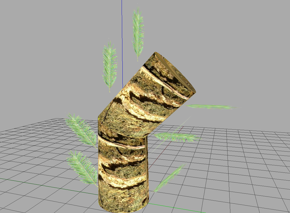
The python script to get a tree with leaves of same size along a bowing trunk is :
from openalea.plantgl.all import *
from math import pi
from math import sqrt


def tree3():

    # We compute the trunk of the tree with an extruded circle
    cyl = Extrusion(Polyline([(0,0,0),(0,0,3),(0,2,5)]),Polyline2D.Circle(1.0,50))
    cyl.solid = True
    tex = ImageTexture("./textures/wood_texture.png")
    trunk = Shape(cyl,tex)

    # Now we compute a leaf. We will use a transparent texture over a square
    points = [(0,-1,-1),
              (0,1,-1),
              (0,1,1),
              (0,-1,1)]
    indices = [(0, 1, 2, 3)]
    square = QuadSet(points,indices)
    tex = ImageTexture("./textures/palm_leaf.png")
    texCoord = [(0,0),(0,1),(1,1),(1,0)]
    texCoordIndices = [(0,1,2,3)]
    square.texCoordList = texCoord
    square.texCoordIndexList = texCoordIndices
    square = EulerRotated(0,pi/2.,0,square)
    square = AxisRotated((1,0,0),pi/4., square)
    square = Translated(0,1.8,1.1,square)

    leaves = [Shape(Translated(0,0,1.6*i,square),tex) for i in range(2)]
    square = AxisRotated((0,0,1),pi,square)
    leaves += [Shape(Translated(0,0,1.6*i,square),tex) for i in range(2)]

    leaves += [Shape(Translated(0,1.6*i*1./sqrt(2),1.6*(2+i*1./sqrt(2)),AxisRotated((1,0,0),-pi/4.,square)),tex) for i in range(2)]
    leaves += [Shape(Translated(0,1.6*i*1./sqrt(2),1.6*(2+i*1./sqrt(2)),AxisRotated((0,2,2),pi,AxisRotated((1,0,0),-pi/4.,square))),tex) for i in range(2)]

    return leaves+[trunk]


scene = Scene(tree3())
Viewer.display(scene)
for the result :